Tone Arm Geometry 101

This drawing explains tone arm basic geometry. Thanks to Wally Malewicz for providing it. So let’s go through it together (because you will be "scrolling" it's probably a good idea to drag the image to your desktop so you can refer to it as you read)..

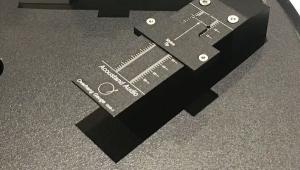
The meaning of the blue line labeled “pivot to spindle” is obvious. If your turntable is factory pre-drilled and fitted with the brand’s tone arm (Rega, Pro-Ject, Music Hall, VPI, etc.) you can be pretty sure the P2S (pivot to spindle) distance is correct but it wouldn't hurt to double check.

If you buy a used ‘table that’s been pre-drilled and fitted with a secondary manufacturer’s arm, it’s a good idea to check the P2S distance either by using a protractor that has a measuring beam (Feickert, Dennesen, etc.) or if you don’t have one of those, by using a ruler marked in millimeters.

The most accurate way to do this is to get a plastic ruler and drill a spindle sized hole in it with the hole’s center at the “0” millimeter mark. If the horizontal bearing’s center is not clearly marked atop the bearing housing (many are not, including Rega’s, Graham, etc.) the best way to get an accurate measurement is to remove the arm altogether and measure to the armboard hole’s center point (that in and of itself is not so easy to do, but it is possible with some effort).

Fortunately, there is some room to compensate for P2S distance error here in the form of head shell slots, which are necessary since the distance from the cartridge fixing screws to the stylus tip has never been standardized (this doesn’t apply to SME arms where the head shell holes are not slotted but instead the arm pivot slides).

Now look at the red line labeled “effective length”. It’s drawn from the pivot point to the stylus tip, which also intersects with the purple arc labeled “arc traced by stylus tip”. Note at the spindle end of the purple arc the green/blue line labeled “overhang”. The “overhang” is literally the amount by which the stylus tip “overhangs” the spindle when the arm is placed directly above the spindle. The “effective length” is equal to the pivot to spindle distance plus the overhang.

Now note the two parallel lines labeled “linear offset”, one well in front of the spindle and the other running from the pivot point and terminating at a right angle with another line drawn through the center of the head shell (and through the cantilever center).

Note the arc labeled “offset angle”. That is the angle formed by the effective length line drawn from the pivot point to the stylus tip and the line running through the head shell and cantilever that terminates at each end at right angles to the two parallel “linear offset” lines.

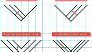
Friction produced by the stylus coursing through the grooves creates a drag force along the dashed/maroon line. Were it not for the offset angle, much of the frictional force would exert “drag” directly in line with the pivot point. However, the drag’s offset from the pivot produces a “component vector force” that “skates” the arm clockwise towards the spindle.

Then why have an offset angle? Because it creates lower HTA (horizontal tracking error) and less distortion. Why? Because as the stylus travels along its entire arc, the cantilever is closer to the groove tangent originally traced by the cutting cantilever/stylus and thus it remains closer to groove tangency.

This geometry produces two “null points” where the cantilever is tangent to the groove. At those points HTA is zero (note: the longer the tone arm’s effective length, the smaller the offset angle. A smaller offset angle produces less skating. That is one of the advantages of a longer tone arm).

Now look at the long and short green radii. In this illustration, the shorter radius runs from the spindle to the stylus, which, at that stylus location along the arc, results in a tangent cantilever to the groove. That point along the stylus tip arc is labeled “In NP” (inner ‘null point’). The radius is also parallel to the two linear offset lines.

Now imagine swinging the tone arm outward towards the “outer groove” and having linear offset and offset angle moving along with it. The second point at which the cantilever is tangent to the groove is the “outer null point”. Mathematically speaking, once you’ve located the "inner null point", there can be only one, easily determined outer null point location.

When you use a gauge or protractor to set the “overhang” you are setting it at one of the two “null points” and possibly confirming it by also checking the second one. For instance, if you have a Rega or Pro-Ject turntable that includes a piece of paper with a pair of grids in which each is located a tiny dot or “X”, those are the two “null points”.

When you achieve a cartridge location in the head shell where the stylus sits on the dot or “X” and the cantilever is parallel to the grid lines of one of the two grids, it will also be parallel in the other grid.

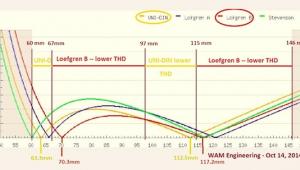
Of course there are numerous possible alignment geometries (Loëfgren, Baerwald, Stevenson, UNI-DIN, etc.), each of which locates the two null points at different locations across the arc and each of which has different amounts of distortion at various points along the arc.

COMMENTS
recordhead's picture

For the last two days I've been trying to make sense out of the proper settings for my cartridge on my tonearm. I pulled out your DVD on TT setup and plan on watching it (again) for a primer. I look forward to reading this tonight.

mlgrado's picture

I never got distortion free sound until I discovered the Arc protractor. They are a God send for setting cartridge overhang for 'challenged' individuals like me. Since I have a Rega table with a known pivot to spindle and effective length, arc protractors with the proper geometry are readily available.

OldschoolE's picture

Thank you for posting this Mr. Fremer! This is the best and easiest explanation of Tonearm Geometry I have seen to date! So now even I understand this! :)
This also makes me more glad that I switched over to an ARC protractor. Doing that even helped me understand a little better, not to mention set up a bit better too. A Turntable set up expert like you I am not, so you have no idea how much this helps....well, actually you do know.
Signed one very appreciative reader!

avanti1960's picture

So if a cutting head has a pivot point and an arc, then there is minimal advantage to a linear tracking table? Do some cutters act like linear tracking turntables?
Final question- what about a pivoting head shell that positions the stylus at 0 HTA throughout the entire arc? Like an old Garrard table that had a push rod connected to the headshell.

Michael Fremer's picture
Cutter heads cut in a straight line. All act like "linear tracking turntables". The Garrard Zero had other issues produced by the pivoted head shell. Another one is the Thales, but that is a far more sophisticated design!
avanti1960's picture

where it read "Because as the stylus travels along its entire arc, the cantilever is closer to the groove tangent originally traced by the cutting cantilever/stylus"
This just seemed a little ambiguous even though I knew cutter heads were tangent. If it would have led with "because it creates two tangent points" I would have never asked the question.

So what would happen if the cutter head did have an offset and a pivot point and that became the standard for turntables to replicate?

ravenacustic's picture

Who several years ago found a used Universal WallyTractor which I bought at a bargain price on Audiogon, I have set up every cartridge with it with outstanding results each time. Unfortunately my aging middle age eyes are making set up more and more difficult and longer and longer to do. But I persevere because the outcome is so outstanding.

mmarston's picture

Cutting heads move in a straight line, along a large screw. The speed of the screw turning is varied to create closely spaced grooves in quiet sections, and greater spacing in loud parts and between individual tracks. Linear tracking arms theoretically can have zero tracking error across the entire disc, but present greater engineering challenges to be made to perform well.

The Garrard "Zero" was another attempt to eliminate tracking error; the concept is valid but the execution was poor. They didn't invent the concept, though; I've seen pictures of at least one articulated arm from the 1950s.

Best regards,
Mike

mmarston's picture

That was meant to be a reply to Avanti1960...

avanti1960's picture

about the linear trackers and their other design challenges. as long as the cutter truly is tangential then a linear design has a fighting chance.
seems like a pivoting head design wouldn't be that tough to execute well- it's pure basic geometry. maybe there are some patents against the application.
all i know is that on my table it's easy to tell when the cartridge is passing through the null point regions. how i wish it would sound like that for the entire record.

MichaelTrei's picture

As MF mentioned, there is a company in Switzerland called Thales that makes three different models of tonearm that rotate the cartridge to achieve zero tracking angle error across the disc. They are however quite expensive.

German tonearm maker Frank Schroeder also makes an arm called the LT which uses a clever mechanism that moves the pivot point of the arm as it plays, with zero offset angle and zero tracking angle error.

One problem with linear trackers, is that they typically have high inertial in the horizontal plane, coupled with low inertia in the vertical plane. So you need a cartridge with an impossible combination of high vertical compliance and low lateral compliance.

thatbobfella's picture

I have a Luxman PX-101 linear TT that has been down a while. Would it be worth pursuing a repair or getting a new unit?
What I mean is which would the vinyls prefer? Have I been torturing them all these years? All TTs would be linear trackers if that was the best, right?

Michael Fremer's picture
But my experience is that generally "linear trackers" have problems and issues that are worse than those of a properly set up pivoted arm.
Michael Fremer's picture
But my experience is that generally "linear trackers" have problems and issues that are worse than those of a properly set up pivoted arm.
OldschoolE's picture

Your absolutely right on that Mr. Fremer. I had a Sony Linear Tracker that would just chew records (needless to say I only used twice). You can't tame them. It had a magnetic drive, believe it or not. Took a long time to get up to speed (about 10 seconds) and the damping was scary. The tonearm (if you could call it that) was about 4 inches long and was P-mount. The needle would come down acting like it would go through the record, but then land gently. When you stopped the record the needle would come up so hard and fast you would think it would fling across the room. Set-up......what set up, the only thing you could adjust was platter speed. No anti-skate, VTF or anything. I bought it new back in 1983 and it was supposed to be the latest thing. Any table today except a Crosley would best it.

tnargs's picture

...plagued by the 'issues' of linear tracking arms that make them all sound worse than the engineering-bodge-up that is a typical pivoting tonearm.

Nonsense, he says. You've been trusting your ears again.

When is the day going to come when MF fesses up and admits that anything we 'hear' while operating our ears in trust mode, is valid and useful for one person in the universe, and only one. And that pretending that there is any generality to these observations is tantamount to deception.

Prediction: never. Make a liar of me. Please.

Michael Fremer's picture
A cutter head and a cartridge have nothing whatsoever in common. A cutter head is more of a brute force operation. A cartridge is quite the opposite. BUT you are a LIAR when you claim I wrote "make them all SOUND worse." I didn't say that. You made yourself a LIAR not I. My point was that both linear and pivoted arms have technical issues. In my OPINION the technical issues plaguing "linear trackers" are for the most part worse than those plaguing pivoted arms.
Atom man's picture

Back in the middle to late 1970s, I had a supervisor whose husband worked as a broadcast engineer for a local TV station and he was a bigger audio addict than I am. She said he replaced most of the electronic parts in a Japanese receiver they had. (I do a little but not that much.) She had played the French horn in a band in HS or College and listened to classical music. They had those large Advent speakers and bought a slim profile linear tracking B & O table. He eventually got rid of it. She said the cartridges were "brittle". Now I think I know what she meant. I saw a bulky, grey Harmon Kardon linear tracker in a store about that same time.

cpp's picture

Does one of these alignment geometries (Loëfgren, Baerwald, Stevenson) better fit a selected turntable and arm to reduce distortion across an LP. Trying to understand which is best for a VPI with a 10.5 arm, on a Classic 2.

georgeincanada's picture

I am very glad I've found Analog Planet! I now became a member; it was more than a couple of days ago that I discovered the theoretical geometry that I was searching to find! I found this web site again, and web page. For the most part most of my questions have been answered, and I am no longer in semi-darkness.

I already have a used harman kardon T25 belt drive turntable that I adjusted, installed a new AT71 stylus. Rear foot is slightly damaged; spring is a bit bent, can't find replacement, new screw threads is wider in diameter. Still horizontally level, checked with bubble level gauges. However, I became very interested in my own turntable DIY build.

I recently bought a Sony tonearm with phono cable from ebay, Canadian. I have received helpful, valuable advice from www.vinylengine.com concerning the soldering of the Sony tonearm to the small circuit board of the phono cable. Then I asked about the distance of the centre of the platter/spindle to the tonearm's centre point. However, no exact measurements could be offered.

Here is the picture of the Sony tonearm that I purchased from ebay: https://www.ebay.ca/itm/Sony-turntable-tonearm-with-Cable-In-Excellent-C...

Anyway, apart from a reference to a Sony tonearm cartridge seller offering advice; as well as the picture of the measurement disc, I want to be as certain as possible to get the distance correct! Therefore, if I find the overhang measurement is it going to determine the exact distance, and angle for this Sony tonearm? I am not certain of the model, number of this Sony tonearm; if I did my job could be much easier.

I have an old Kenwood KD-26R belt drive that I was planning of dismantling. Most likely I am going to use its motor; maybe the circuits for the 2 speeds of 33.33, and 45 RPM. I tougher, more complicated work.

Or I was thinking of buying a "Project 60Hz Turntable Pulley" from ebay. On Internet turntable motors have that small brass pulley, but how am I going to remove it, then fit motor's axle to that 60Hz Pulley? Seller did not answer that question yet. Furthermore, to simplify things, and make it safer, I was thinking of connecting the motor to a case, switch with a 9 volt battery, anyhow.

Thank you for your time, consideration; and thanks for your patience in considering this very long question.

Sincerely,

georgeincanada

X