And then what?
I feel like i am missing something, the "and this is how to correct it or deal with it being wrong".
Zenith Angle: The Final Cartridge Set-up Frontier?

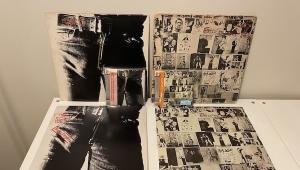
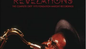
First up: identifying the two John Lee Hooker files in The Tapestry reveal: "File 1" is the original pressing. "File 2" is the Analogue Productions 2010 double 45 reissue. Some preferred the reissue, clearly cut from a secondary source, lured by the added bass and top end intended to distract from the soft guitar transients, vocal cloud and lack of top end air and having locked into that, those listeners found the original pressing "bright" and "bass shy". It's a tricky business but while the original may have had the bottom cut slightly it is otherwise massively superior and over time far more listenable. Now on to a really interesting and important test!
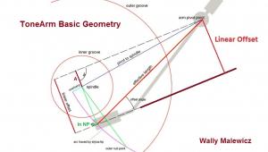
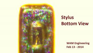
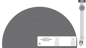
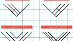
WAM engineering's J.R. Boisclair offers a cartridge evaluation program that I'll discuss in greater detail in an upcoming "Analog Corner" column in Stereophile. He examines new cartridges for stylus rake angle, azimuth and zenith angle. While he offers custom made shims made with a material nearing the rigidity of titanium that can correctly set stylus rake angle and azimuth (meaning if your arm doesn't allow for those adjustments the shims can), there's no shim solution for zenith angle. For those unfamiliar, when you use a protractor or other "overhang" device, you set "overhang" (the distance between the stylus tip and arm pivot) and then, using the gauge's "null point" markings (where there is "0" LTE (lateral tracking error) you align the cartridge so that the cantilever is parallel to the gauge's "hash marks", which is the "zenith angle."
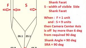
Unfortunately, as Mr. Boisclair has discovered, the way styli are inserted into cantilevers can produce up to 7 degrees of error. That is large ! Of course if you use a spherical stylus it doesn't make a difference but you are missing a great deal of musical information that if you are unaware is there, you don't miss. Your loss! But if your cartridge is fitted with a "line contact", "hyper-elliptical", "fine line", "Replicant" or "Gyger" type stylus, if the "contact patches" are not perpendicular to the cantilever, using the cantilever to set zenith angle can produce a major set up error! According to Boisclair's research, cantilever/stylus manufacturers allow for up to 4 or 5 degrees of manufacturing error, which they claim is "acceptable" and reasonable given the difficulties involved.
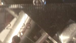
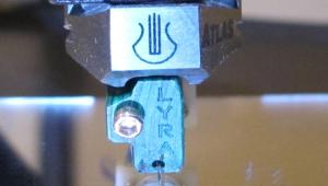
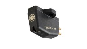
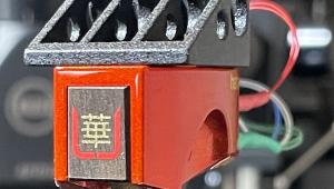
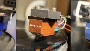
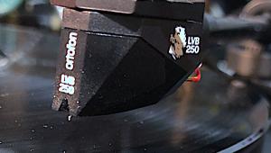
This image shows a cantilever/"Fine Line" stylus assembly that has a 3.83 degree from perpendicularity error based upon average of multiple measurements (the one I chose from the multiple images shows 3.15 degree error).
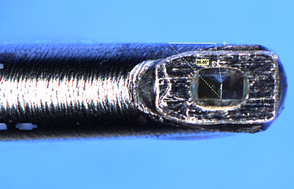
So, with this cartridge, when you set your zenith angle using the cantilever as a guide, your set up will produce around 4 degrees of zenith angle error, meaning the stylus will read the left and right groove walls at slightly different times, which is only one of the errors produced by this kind of misalignment. Is this audible? The cartridge here is an outstanding and costly Haniwa CO moving coil cartridge, which uses a Ogura stylus/cantilever assembly used by many, many other cartridge manufacturers including Lyra, My Sonic Labs, etc. This report is not meant as a criticism of Haniwa or even of Ogura. This cartridge is within the reasonable manufacturing tolerances set by all (there are only a few) manufacturers of these components.
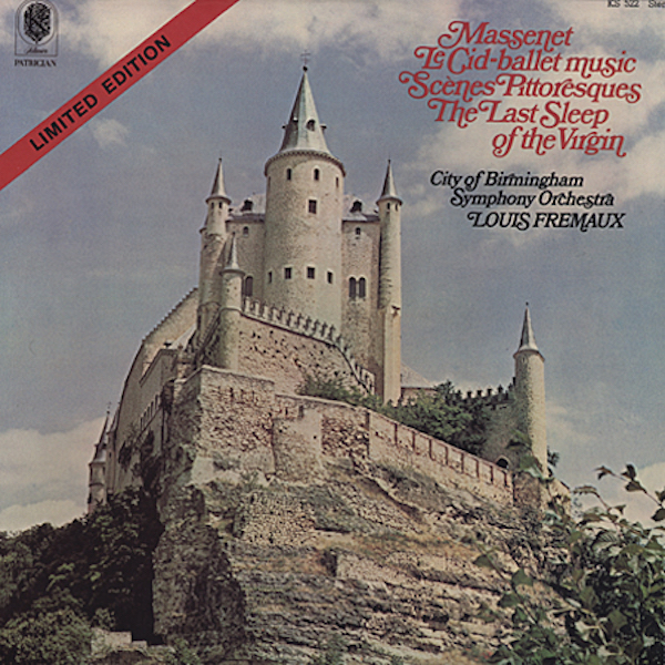
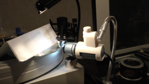
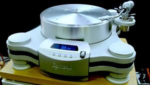
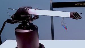
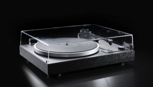
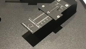
So, after installing the cartridge (which, by the way has a super low internal impedance and tracks as low 1 gram) in an Acoustic Signature TA-7000 tone arm on the A-S MontanaNEO turntable with all parameters correctly adjusted but with the zenith angle set in the "traditional" visual manner, I played and recorded the final few minutes of "Le-Cid Ballet Music" from a 1973 certified audiophile classic—a reissue of an EMI original produced using the "One Step" process (nothing new under the sun!) and so limited to 1000 copies per stamper (meaning they had to cut a new lacquer each time)—and then, using the information provided by WAM Engineering in its cartridge report on this particular cartridge along with the Wally Zenith angle gauge, I twisted the cartridge in the head shell to line up with the purposely "off kilter" hash marks on the zenith angle gauge and again recorded the music. Remember: nothing other than the zenith angle was changed.
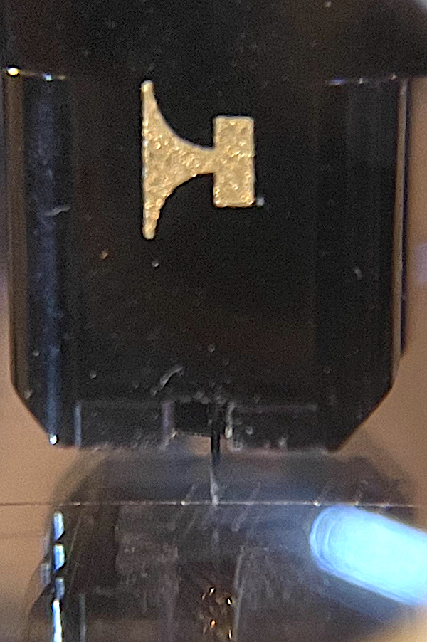
The first image is obviously the album cover. For the second image, after using the zenith angle gauge to twist the cartridge in the head shell, I returned to the platter the standard WallyTractor overhang gauge and placed the stylus on the "null point" hash marks so you can see just how far from parallel to the hash marks was the correct setting. Keep in mind that this image shot through a magnifying glass is distorted and does exaggerate the angle but by less than you might think. In other words it looks very wrong !
Finally, here are the two files. Do you hear a difference? If you do, which do you think sounds better? And please, if you choose to listen on "computer speakers", please don't bother commenting. Thank you.
- Log in or register to post comments

"In other words it looks very wrong!"
Submitted by ivansbacon on Wed, 2022-03-09 12:03

Look Very Wrong
Submitted by Michael Fremer on Wed, 2022-03-09 13:38
In part because of the loup distortion and partly because it's 4 degrees shifted to correct for the error in stylus insertion. It does not look particularly "wrong" when playing records!

We have to aware that
Submitted by jazz on Wed, 2022-03-09 12:59
this awful zenith tolerance means, all past anal optimizations of cartridge alignment were dog poo. We might have been much better off with a “misaligned” cartridge. Audiophiles are poor lemmings of each new topic run through the roost. But I believe every word of this zenith thing unfortunately.
Right, we take the best we get.
Submitted by jazz on Wed, 2022-03-09 14:32
But it’s still strange we buy expensive protractors to align everything to a crazy detail level and persuade ourselves (reviewers included) how much better this adjustment sounds than a slightly different one, just to recognize years later, that this was plain nuts in most of the cases because each of those adjustment options was probably wrong.
It will be interesting how we can adjust the zenith problem with a detail level usual at the best protractors. This is difficult to imagine, given the short geometric lines of the stylus to orientate on and the missing accuracy available when compensating with cartridge adjustment.
The tolerance mentioned is simply not suited for the application, especially in case of fine line styluses.

Wouldn't be advantageous
Submitted by KLW on Wed, 2022-03-09 16:12
for all cartridge manufactures to use some sort of standardize guidelines for acceptable finished needle insertion and Zenith angle? Across all brands.....Acceptable variations etc.? Also would be nice to have a small diagram showing offset angle of the inserted/set needle for the specific cartridge you have purchased. Or at least Maybe "graded" versions of the same model (with different prices).

All expensive cartridges should be so measured...
Submitted by shawnwes on Sat, 2022-03-12 05:28
...before they leave the factory with deviations from ideal noted for help in getting the most out of the setup process. Not complaining about about the cost of their service charges but having to spend an additional $500 with a 3rd party service provider on top of the purchase price to find out the builder did a mediocre job of aligning your stylus tip seems akin to purchasing a second hand Ferrari!

I'll Play
Submitted by 2_channel_ears on Wed, 2022-03-09 17:37
Overall I prefer file 1. This was a bit of a tough call but it had a bit more "air" to me and dynamic range. It sounded like maybe an old record to my ears. File 2 was cleaner but a bit muddled in the mids. The big ending was telling to me too; #1 all the way.
Compounding error?
Submitted by The Walrus on Wed, 2022-03-09 19:47
I love this kind of analysis/insight - if you're a bit OCD like me (also I am a mathematician) - these things are super interesting!
Question though - wouldn't this manufacturing variance also exists in the manufacturing of the cutting stylus? Could this "correction", in some scenarios potentially make matters worse? For example, if the cutting stylus had the SAME offset (resulting in an imperfect groove to start with) - would offsetting your playback stylus possibly make matters worse?
The game of chasing averages continues!
Very good point.
Submitted by jazz on Wed, 2022-03-09 23:08
We seem to optimize the non solvable. At least not to the accuracy we had in mind so far.
Funnily enough, in this situation linear tracking arms not even have the chance to be really correct at randomly arising points of the record surface.
When we then also see how we optimize SRA to the degree, assuming that at least each label of the originals we hear had a different cutting angle used, we may feel quite silly with our intended grade of accuracy.

that is the right question to ask
Submitted by WallyTools - WA... on Thu, 2022-03-10 08:09
Of the three axes the recording engineer needs to be concerned with (azimuth, zenith and rake), most lathes only offer freedom of control on the rake angle. What is absolutely certain is what the cutterhead stylus SHOULD be aligned at: perfectly collinear to the radial line of the lacquer (zenith) and perfectly perpendicular to the lacquer (azimuth). Those are beyond debate. Ideal rake angle is up for debate.

I would expect a cutting stylus...
Submitted by miguelito on Thu, 2022-03-10 09:33
To be manufactured more carefully. The sizes involved here are not small by manufacturing standard. I am pretty sure you can easily get extreme precision on stylus alignment for a cutting stylus. It is different if you're making 1000 cantilever-stylus assemblies a day that you can sell for $1 a pop.
I have three waiting for analysis right now.
Submitted by WallyTools - WA... on Thu, 2022-03-10 09:39
Joe Harley sent me three cutting styli that I'll be analyzing later this month with an optics expert at my side. I'm looking forward to that.
Not Zenith
Submitted by scottsol on Thu, 2022-03-10 01:17
Your files are not helpful. As is confirmed by the title graphics, a listening test for horizontal alignment can only be properly performed using a Micro-Touch 2g Tone Arm.
further reading for you
Submitted by WallyTools - WA... on Thu, 2022-03-10 08:16
Hi Scottsol,
I wonder if you may be helped with a bit of background first. Read this: https://www.wallyanalog.com/post/zenith-error-the-final-alignment-frontier
Missing historical context
Submitted by scottsol on Wed, 2022-03-23 18:01
There was never a question of your mathematical analysis. What’s missing, according to my mirthometer, is a full application of the historical provenance.
That is FANTASTIC!
Submitted by WallyTools - WA... on Wed, 2022-03-23 21:50
I love that video! So funny. Thanks for sharing that.
That cantilever is completely off
Submitted by miguelito on Thu, 2022-03-10 08:03
Looks to me like no antiskating maybe? How could you possibly be zenith aligned in this situation?
Which BTW highlights that alignment needs to include adjustment of antiskate with a record playing
Correct!
Submitted by WallyTools - WA... on Thu, 2022-03-10 08:13
I have a very telling video that I show in my seminars of how much the cantilever offset angle can change with and without skating force present. In my one and only experiment of this nature the answer was clear: 2.4 degrees. That is a pretty good argument for fighting that skating force with anti-skating force!
As to your first question, if you take a close look at the WallyZenith (https://www.wallyanalog.com/wallyzenith) and how the alignment marks are laser cut, you'll see how it accomplishes the task of setting the contact edges of the stylus to be perfectly collinear to the radial line of the record by purposefully "mis-aligning" the cantilever in an amount equaling the zenith error but in the opposite direction.
I think the procedure should be...
Submitted by miguelito on Thu, 2022-03-10 09:43
1- Set anti-skating such that the cantilever is NOT deflected when it touches the record groove (with the record rotating of course)
2- Set the anti-skating to zero
3- Use the Wally Zenith to adjust to the desired cantilever angle (if you kept the antiskating on, resting the stylus on the tool would deflect it)
4- Set antiskating to the value in 1
Enjoy...
WAM's cartridge analysis....
Submitted by miguelito on Thu, 2022-03-10 09:20
Makes a lot of sense to me, either to understand that a cartridge needs fixing or getting shims to set azimuth and rake properly.
As for zenith, the Wally tool allows you to set the angle statically, but one probably needs to adjust antiskate first - to keep the cantilever straight - then adjust the cantilever angle.
In all these cases, if the adjustment is large, you're going to end up with a misaligned armature, which is as detrimental to the sound as the misaligned stylus.
On shimming...
Submitted by miguelito on Thu, 2022-03-10 09:28
No this is not a dance move... :)
Being an SME V owner, I have no way to adjust azimuth. However, I have come to the conclusion that doing so with a shim method - I use folded aluminum foil - is much more precise and rigid than loosening up a screw and more or less blindly turning the headshell or arm wand around, without any scale to refer to. With the said aluminum foil method you can say "10 folds on the right give me this much change in the output signal on the left vs the right" and then do a little math to figure out exactly how many folds you need. That is precise.
Watch this video from about 2:50
Submitted by WallyTools - WA... on Thu, 2022-03-10 09:54
Because the thread pitch of a 2.5mm screw is known, we can actually measure your ideal azimuth angle with a simple allen key. This then makes repeatability easier then measuring each time.
Maybe I don't understand your comment, but I'll try to respond
Submitted by WallyTools - WA... on Thu, 2022-03-10 09:47
Skating force requires friction to be present. During setup there is no friction and therefore no skating force and therefore no need for anti-skating force. If you set anti-skate first you will cause the horizontal force to deflect the cantilever into a new clockwise error position (perspective from front) which you will then align for by twisting the cartridge counterclockwise (perspective from above). If you do this, when skating force kicks in it will skew the cantilever counterclockwise (perspective from front). You have now DOUBLED your tracing error.
So I meant to say...
Submitted by miguelito on Thu, 2022-03-10 10:00
I think you need to determine your needed anti-skating dynamically (with a record playing) by seeing what is needed to keep the cantilever straight. Then SET IT TO ZERO and use the WallyZenith - agree you want NO skating force when using the WallyZenith. Then once you're done setting the zenith you end the process by setting the anti-skate to the value determined in the first step.
Is that right?
I like the idea in spirit but...
Submitted by WallyTools - WA... on Thu, 2022-03-10 10:49
...in practice would be nearly impossible.
Assume you set up a USB scope to inspect the cantilever angle whilst playing a record. To what would you align the cantilever against since the record itself certainly won't have a reference alignment mark? I suppose you could put a reticle in the scope itself and find a way to perfectly level the scope, but then how would you confirm you have eliminated parallax error? Even if you managed to do all this, at what playing radius would you measure this angle since skating force varies by playing radius? At what groove amplitude/coefficient of friction?
We ruefully accept that anti-skating is an approximation at best but we at least know the min/max skating force generated based upon playing radius and groove amplitude and are content to know the range isn't HUGE.
Fair enough...
Submitted by miguelito on Thu, 2022-03-10 12:44
When the antiskate is off, I have seen the cantilever bend just like in Fremer's pic. But I get your point that as soon as you have some anti-skate, determining the "perfect" antiskate by aligning the cantilever is pretty difficult to do since the record has to be moving.
Is your estimation that the deflection due to anti-skate pull is small if the anti-skate is set roughly ok?
on average...
Submitted by WallyTools - WA... on Thu, 2022-03-10 14:15
...the applied anti-skate force makes a 1:1 counter to the skating force. If memory serves me correctly, the skating force can vary by about 50% from "nominal" under normal playback conditions (i.e., not unrealistically highly modulated grooves). This means that if your VTF is 2.0gm, your anti-skating force should be about 0.2gm and the skating force will vary between 0.10gm and 0.3gm. If we assume the cantilever is perfectly aligned at the null point with 0.2gm "nominal" skating force the question becomes, "how much will the cantilever deflect from tangential position if the skating force is 0.1gm or 0.3gm with 0.2gm anti-skating force applied?" I don't know, but I know it is calculable and will involve knowing the horizontal dynamic compliance, the vertical tracking angle and a couple other factors. Since I've measured a 2.4 degree change in cantilever angle static vs dynamic you might infer that the change in cantilever angle will be less than 1 degree from highest to lowest skating force conditions. (You have to account for the fact that compression resistance of the suspension damper increases significantly after the first bit of force is applied which means that, say, the first 0.01gm of horizontal force will cause much more deflection than going from 0.19gm to 0.20gm.)
***However, few have ever considered the "beneficial" role of tracing error that occurs at the inner area of the record!***
Here's what I mean by that: At the outer area of the record where skating force is at its highest (using IEC innermost/outermost groove standards), tracing error is in the same direction as the pull of the skating force. In other words, if skating force is very low the anti-skating force will have a tendency to pull the cantilever outwards and make a slight "correction" of the tracing error. If skating force is high, the tracing error at the outer area will be exacerbated because the skating force is causing the cantilever to shift in the same direction as the tracing error. However, tracing error is not as much a problem at the outer area of the record due to the high linear groove velocity and therefore a low density of signal in the groove for each linear unit of groove distance. The stylus could be out of alignment by a couple degrees and it wouldn't be nearly as noticeable as it would be at the innermost grooves where signal density for a given unit of linear groove distance is much greater.
However, at the innermost groove area, the natural tracing error that occurs with pivoted tonearms is "partially corrected" by the increase in skating force which starts to lift quite quickly in the last few millimeters of the playing area. In other words, the tracing error at the innermost area is clockwise from its ideal position but the increased skating force due to the short playing radius (and probably the greater signal amplitude/coefficient of friction that often accompanies the end of recorded material) forces the cantilever in a counterclockwise direction which helps to ameliorate the tracing error.
This is yet ANOTHER reason not to use Stevenson alignment. Be advised, Rega tonearm users!
By the way, we have acquired all the equipment to re-do the coefficient of friction tests done decades ago. To truly calculate skating forces generated, these tests need to be updated using modern vinyl formulations and the much more common (today) severe stylus profiles. We need to finish one or two other studies before we get to this one. Stay tuned.
Fascinating
Submitted by miguelito on Fri, 2022-03-11 05:50
Great points on tracing errors across the record. Most connosieurs would tell you less antiskating is more. Your arguments point to the opposite here, which is interesting. Any insight on why some advocate for less antiskating?
On deflection vs force: I did a study with my Dynavector XV-1s and a USB microscope. What I found is that 2.2gr of VTF deflects the stylus by 3deg4min. Assuming a symmetric suspension, this would roughly mean that the side deflection for 0.1gr force would be about 0.3 degrees. So roughly speaking your range 0.1-0.3 would mean a variation of +/-0.3deg in the cantilever angle due to those lateral forces.
Sorry... Too early to do math!
Submitted by miguelito on Fri, 2022-03-11 05:53
Side deflection would be +/-0.13deg - very small compared to the corrections you're implying with the WallyZenith which seem on the order of 2-3 degrees at times.
Before you did this test…
Submitted by WallyTools - WA... on Fri, 2022-03-11 07:05
… did you confirm that your tonearm was free of its own internal horizontal force acting upon the cantilever by using a WallySkater?
Yes I did check that there was no residual antiskating
Submitted by miguelito on Sat, 2022-03-12 20:43
By setting antiskating to zero AND VTF to zero so that the arm would float and not be deflected horizontally I also have a black disc but I have found the other method is more sensitive.
I shouldn’t type faster than I think!
Submitted by WallyTools - WA... on Fri, 2022-03-11 07:24
There was an error in my thinking on one of the bits above. At the innermost area of the record the angular error of the cantilever (and therefore tracing error) is in the SAME direction as the increased skating force. This error is worse if you are using Loefgren versus Baerwald.
However, having measured and documented 1300 records for the innermost groove, I am still very unconcerned about the additional tracing error that increased skating force would cause in this area of the record. This is because by the time skating force gets high enough to exceed the anti-skating mechanism ability to keep up with it, the vast majority of records have ended the musical content. Add to this the fact that most anti-skating mechanisms and increased tonearm wire torque cause an increase in anti-skating force at the inner area of the record.
Sorry to cause confusion. It is an interesting fact about tracing error in tonearms with an offset angle that the tracing error starts from the outer area the record in counterclockwise error, in the center of the record becomes a clockwise error and ends the record with another counterclockwise error. (Perspective: viewing the cantilever from the front of the cartridge.) This is exactly why the WallyTractor includes instructions to visualize the cantilever at the points of maximum angular error (clockwise and counterclockwise). This process helps train the user to identify what less than 1° of angular error looks like. Without this reference of being able to visualize less than 1° of angular error, most new users assume they have aligned the cantilever “good enough“. When they see the maximum angular error points, new users tend to return to the null points to improve the alignment. As familiar as I am with proper alignment of the cantilever, I use these maximum angular error points regularly during set ups.
El Cid, One Step
Submitted by Rodan on Thu, 2022-03-10 12:00
File 2, but it's really close. The fact is that I'm not sure I will be able to correct--or even identify--the zenith error of my various cartridges; however, your article does make clear that manufacturers' "acceptable tolerance" probably needs to be tightened, especially given that quite a few cartridges are REALLY expensive.
I do want to make a slight clarification to your statement that '"Le-Cid Ballet Music" [Klavier KS 522] . . . produced using the "One Step" process and so limited to 1000 copies.' When I read that, it didn't seem to correspond to what I remember of my copy of that LP, so I went to my record shelf and found that the "Limited Edition Seq.#" on my disc is 2601. How is that possible? Because up to 1000 discs were pressed from EACH stamper. To quote from the jacket: “Single step process was used for this ‘Limited Edition’ release. The stamper was made from the first generation master and not more than 1,000 were pressed from each stamper. This process allows every record to be of ‘test pressing quality.’” I'm not sure what my particular disc's number means--but I know it's more than 1000!
Keep up the good work.
Yes I Read That But...
Submitted by Michael Fremer on Thu, 2022-03-10 15:54
I assumed they made a mistake in the description because otherwise they'd have to cut a new lacquer for each 1000 records pressed, and I guess that's what they did. My copy was under 1000. Had it been in the 2000s I'd have known better! Thanks..
I tonally prefer file 2, in
Submitted by maxbara on Sat, 2022-03-12 09:40
I tonally prefer file 2, in file 1 sometime strings become a little harsh, in file 2 there is more weight on the right channel. Just my 2 cents
Anyway soundstage is wider in
Submitted by maxbara on Sat, 2022-03-12 10:18
Anyway soundstage is wider in file 1, but in my setup the woods on the right are not so clear.
Who knows..
It seems to me that if a cartridge has a misaligned stylus
Submitted by Analog Scott on Sun, 2022-03-13 09:56
You ultimately have a porblem one way or the other with your geometry. Canitever geometry does matter. So if stylus geometry has to be wrong for cantilever geometry to be right and visa versa you have problems either way. I'm thinking a better solution would be a correction DSP filter. Of course that would be very unpopular among the "all analog" folks. I don't know if such a DSP even exists or if there is much of a market for one because of the fear of digital.

Not close for me
Submitted by kkatseanes on Sun, 2022-03-13 19:20
It's #2 for me, in every way. # 1 is shrill, the cymbals are far to bright, the triangle has no richness, and at the end the castnets are not so much richer and fuller sounding in no. 2. Also the bass is much richer. The most intersting response for me was this, as I listened to no. 1 I thought "sure don't like this piece very much." Then when I listened to no. 2, it was the opposite reaction "I wish I had this record. I like the music." No. 2 was so much more musical and timbre correct and listenable. Now I am super interested to see what can be done to ensure my cartridges can be aligned with correct zenith. Is there anything short of sending it in to J.R. to get this right?
castanets "are" so much richer and fuller in no. 2
Submitted by kkatseanes on Sun, 2022-03-13 19:23
Sorry for the typo. Everything was richer in no. 2, for me, including those lovely castanets that emerged at the end.

"Zenith" logo hopefully not a bad omen...
Submitted by Mile High Audio on Mon, 2022-03-14 13:08
Hopefully using the old "Zenith" electronics company logo - mainly a major USA video company that shriveled to be a tiny tech licensor - is not a bad omen. Fingers and tech tools crossed! :-)
Zenith angle
Submitted by Click and Pop on Mon, 2022-04-18 08:52
Sorry for coming late to this discussion.
I'm hoping someone here can address whether the time phase misalignment of the left and right channels created by zenith error would be measurable with a 2-channel oscilloscope while playing a test record, and if so, how expensive such an oscilloscope would be? Thanks!


| Equipment Reviews | The Gruvy Awards | Blogs Analog Tips | Columns Music | Show Reports | News Resources |
 © 2025 AnalogPlanet
AVTech Media Americas Inc.
All rights reserved