That Crazy Little Thing Called "Azimuth" Part 2

In Part 1 we explained the importance of proper azimuth setup. Now, on to how to achieve it! While using a digital oscilloscope is the most accurate method, it also requires you to spend hundreds of dollars to buy one and then you have to learn how to use it. That's not really necessary for most analog devotees, and so we're not going to go into the details here. If you insist, you'll have to buy one and figure it out using the methodology that will be described, which is generally applicable to whichever way you choose to go.

First, you need an accurate test record that includes separate left and right channel 1K (1000Hz) modulated grooves. 1K is the standard frequency used to measure crosstalk. These include Analogue Productions' The Ultimate Analogue Test Record(AAPT 1) and the Clearaudio Azimuth Optimizer Test Record. I've used the first one but have not yet tried Clearaudio's. The goal is to measure the output of both the modulated and unmodulated channels of a test record that includes separate left and right channel modulated grooves. When you play the modulated left channel test track for instance, you can measure the output as a voltage and you can also measure the channel that's not supposed to have any output since it's unmodulated. Of course this is the real world so there will be some crosstalk and some voltage generated, but it will be much lower than the modulated channel. Keep in mind that the results can only be as accurate as the test record and test records too are not perfect.

So here's the least expensive way to do this. First you will need an accurate digital voltmeter. This should cost no more than fifty dollars. Then I recommend some decent earplugs. You'll know why shortly. If you know how to build a high and low pass filters, that will make the results more accurate and easier to obtain, but don't worry, even if you don't you'll get sufficiently accurate results to make doing this very worthwhile.

(However, if you can build such filters build pairs of high pass 500Hz and low pass 2kHz filters with two sets of speaker terminals in a project box, connecting the filters to one pair that will act as the box's input. Run two pairs of short length speaker cables (in this instance lamp cord will do!) from the amp to the box's inputs and connect the voltmeter to the box's output terminals to run these tests. If you're comfortable doing so, put load resistors across the terminals and then you can run these tests with the speakers disconnected, which will obviate the need for earplugs

Whether or not you've built the box, the next step is to set the voltmeter to low AC volts (around 5 volts) and put the probes in the left channel of your amplifier's speaker terminals. Play the test record's left channel modulated band and after putting in the earplugs, turn the volume up until the voltmeter reads around 4 volts. Because of rumble and other additive distortions, the voltmeter will not remain steady at 4 volts so you'll have to 'average' it to where the meter dances back and forth evenly around 4 volts.

Now, while the modulated left channel test track is playing, move the probes to the right channel and measure the voltage. It should be very low, in the range of .15 volts. Write down the large voltage number and small voltage number.

Now, repeat the test using the right channel test track while leaving the probes in the right channel speaker terminals.Be sure you don't move the volume control on your preamp! Perhaps you'll note a slightly lower or higher reading indicating that the cartridge's output isn't identical for both channels. Write that number down and while the same test track plays move the probes to the left channel amp terminals and write down the smaller voltage.

Now you have two sets of numbers. Use the chart below (which you should copy, paste and print out) generously donated to this site by Mr. Wally Malewicz, to convert the large voltage left channel and small voltage right channel to dBV and do the same for the right channel.

So, let's say you measured 4 volts on the left channel and then .14 on the right. The closes to 4 volts is 52dBV. The closest to .14 is 23dBV. Subtract 23 from 52 and you have 29dBV. That is the left channel separation. Now repeat using the right channel information. Chances are the final number will not be the same. If they are, you've lucked out! But don't count on it.

Acceptable crosstalk is around 25dBV left to right and right to left. Good is 30dBV and above that is very very good! But you are not done. If the difference between the two channels is greater than 3dBV you need to adjust azimuth setting. If you can make a tiny mark on the arm tube to serve as a reference starting point, do that.

However it's done on your arm, slightly rotate the arm tube (or headshell, etc.) in one direction (doesn't matter which) and run the test again ( I didn't say this was easy or fun!). If the new results show a worse result, you've gone in the wrong direction. So return to the original setting and then rotate further in that direction and test again.

If the first azimuth change narrowed the difference, you’re going in the correct direction. If you’re within 10 percent, you can leave it, or move it a bit more in that direction and measure again. If you’re even closer, good! If not, you’ve gone too far and will need to head back in the other direction until the two dB values are within 10% of each other. (Don't be surprised if the large voltage output changes slightly as you rotate the arm tube and make measurements).

Then you’re done. You’ve minimized and equalized as best as possible the crosstalk, thereby maximizing channel separation.

You should now hear a wider, better balanced, more symmetrical soundstage. If your initial result was sufficiently off, after correcting the azimuth you will probably be shocked by the improvement. Your jaw may drop so have a basket handy. Can we please from audio review writing phrases like "jaw dropping" and "veil lifting" (unless you are a reviewer for Taliban.com)? Please?

If you are really interested in this subject you might try running this test beginning at, say, 3 degrees to one side of perpendicularity and then every half degree or so toward perpendicularity, then perpendicularity and then to 3 degrees to the other side and then checking the results.

Don't be surprised or shocked to find the best result is not with the cantilever perpendicular to the record surface! However, if the result is way to one side (more than 1.5 degrees or so) and you've recently spent more than $1000 for your cartridge, I'd contact the manufacturer for a replacement (if it's new).

You can also use a Fozgometer ($250) to set azimuth. The procedure for using this device, invented by surround sound matrix inventor Jim Fosgate, is similar to what's just been described, but the results are relative and don't give you precise crosstalk numbers.

You can also use Dr. Feickert's Adjust + software. It costs a few hundred dollars and provides you with charts that plot the results as you rotate the arm tube. Use that link to learn more about it. You have to learn how to use the software and it's Windows only. However, the record Feickert supplies is not recommended.

Well, that's it! Please do try this at home and let us know what you hear!

P.S.: even if your tonearm doesn't allow for azimuth adjustment, run the test once to see how well your cartridge is manufactured and what kind of separation you are achieving.

COMMENTS
floweringtoilet's picture

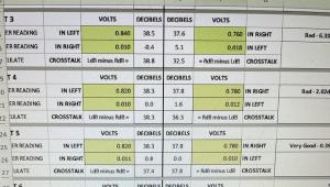
Could you follow the same procedures, but rather than using a voltometer, record output to a computer and take the measurements in an audio editing program? The only issue I can think of is that because digital audio uses 0 dB as max, you'd have to account for the fact that you'll be dealing with negative numbers for your dB measurements (but no need to convert volts to dB). You could also use the the audio editing program to create the high and low pass filters digitally. Is there any reason why this wouldn't also work?

Thank you for the informative write up!

Martin's picture

Cool, I like that you're doing this with a $10,000 cartridge!!!  

I'd want to hope that thing is straight.

I remember doing this shortly after I set up my turntable, using the instructions that came with your first DVD. I came up with as I remember something over 30dbv channel separation. The cartridge is a Lyra Skala - bought partly on your recommendation back then - and SME V tonearm. You thought it would work synergistically, I think it does, sounds great.

Anyway, the SME tonearm is straight :)

Michael Fremer's picture

Yes it is. The issue for SME owners is, is the cartridge "straight"! Because if it's not, you can't adjust azimuth. Lyra's built quality is superb, but even they rely upon the built quality of the stylus/cantilever assemblies they purchase from outside sources. You obviously got a great one!

roscoeiii's picture

I've also seen it suggested that if azimuth is off on a Rega or SME arm that doesn't have built in azimuth adjustment, users can add small thin washers on one side or the other of the cartridge or base to rotate the cart to a degree that will improve azimuth. 

Michael Fremer's picture

Yes, some people suggest that. Someone once suggested using a piece of pencil lead (very thin) that you put between the cartridge and headshell. Then you can roll it back and forth until you find the right azimuth setting. I've never tried that but you do lose the tight contact between the cartridge top plate and the headshell.

alrau@juno.com's picture

I suggested the pencil lead to you, but I adjust the azimuth by tightening the screws "unevenly" to achieve the desired position.

Rob's picture

Great article, Mikey. I certainly dig these instructionals you're putting up.

For those that don't have adjustable azimuth on their tonearms - perhaps try the Ortofon Cadenza range of cartridges. They have a wedge incorporated into the middle of the cartridge that acts as pivot point. By tweaking the screws you can get more than enough adjustment to fine tune the azimuth.

jeff0000's picture

Mr. Fremer:


Will you be reviewing the Moon LP810 Phone Pre-amp any time soon?

Sorry that I couldn't locate anywhere on this site to start a new subject.

Thank you,

Jeff 

mauidj's picture

Aloha Mikey...don't forget there are SME's that have removable, thus slightly twistable, headshells. That's why I bought a SME 312S instead of a V12. I've read that it gives up some things to the V-12 but do you think it is made up for by it's adjustability?

I look forward to using your azimuth alighnment methods on my Soundsmith SG cartridge when it returns from it's repairs.

This is just what I needed...many mahalos Mikey!

Layums's picture

Hi. Great write up mikey as usual. 


Can anybody point me towards a website with som instructions on how to make one of those things. I'm interested in getting my azimuth spot on. 


Thank you

rlw3's picture

the fosgometer i have takes a signal directly from the turntable or from the phono preamp output. Your Wally/voltmeter method takes a reading much further downstream at the amp output. Are results measured further downstream more suspect because of the extra potential of a lengthier "trip" to reduce the accuracy if there is any difference of output due to the preamp or amp?

lakeallen's picture

I have a Rega RB700 arm witha Benz H2 cartridge and my Fozgometer showed it quite a bit off on azimuth. I used 3 paper "holes" from a paper hole-punch on one side and improved azimuth, but it's still not real close . I purchased the Benz rebuilt and think it's off alignment, not the arm.

nknm's picture

I don't get it. How can you connect the volmeter's probes to the amplifier's speaker terminals when the speakers are connected to the amplifier?

vince's picture

Best to use a dummy load, if you want to measure the amplitude at the amplifier's loudspeader terminals.  The dummy load (typically an 8 ohm power resistor) does not have any (ok, much) reactance and offers a stable way to load the amplifier while you take voltage measurements.  Measure the voltage drop across the resistor.  Some amplifiers will go into oscillation if left unloaded.  This isn't good for the amp.  

I made a little box, with two power resistors, to load the amp (one resistor for left, and one for right).  I put some taps on it, specifically for the purpose of measureing the voltage across those resistors.  As a (nearly free) bonus, I put a couple 300 ohm resistors in the box to power a headphone jack (and thus a pair of headphones).  Now my loudspeaker amp can also, safely, drive headphones.  The 300 ohm resistance was just a guess.  The nice thing is that you can make iterative guesses and optimize the output resistor for the headphones and get the best tone.  The whole kit was less than 200$, including a nice project box.  I'm sure it could be done for less than 100$ if you shop a bit.  

Another place to measure is at the output of the phono stage.  Or at a tape out.  Most DMMs have the capability to measure millivolts and will measure at these locations just fine.  You will want to build an RCA to banana plug cable to interface your amp to your DMM for these locations.  Cheaper than the project listed above, but alas, no headphones capability.

Siana's picture

First off, this sentence doesn't parse: "Can we please from audio review writing phrases[...]". I think you just the whole Internet.

I wonder whether it's possible to measure crosstalk with a more widely available record. For example a Serato or other DVS control vinyl, by employing computer analysis. The vinyls almost don't cost anything. The composition is usually following. Two channels play the same frequency offset by 90°. 1 KHz for Serato, 2KHz for Traktor, 1.2 KHz for Mixvibes - all of these frequencies are roughly suitable. This is not sufficient however, because on simple 90° out of phase sound, the crosstalk will simply amount to reduction of amplitude. Most of the time, they play at the same power. Low-bandwidth digital signal is amplitude-modulated onto periodic parts of the signal, making the amplitude in one or another channel, but not in both, drop in half. Can sufficient conclusions be made from that at all?

It's likely that you won't be able to tell apart crosstalk and distortion, and you will never get an absolute measurement, but if your goal is to minimize crosstalk and minimize distortion, this might be sufficient? Signal analysis experts, raise paws!

Joe Crowe's picture

I know this is an old thread but relevant to today's project. I notice at the end Adjust+ is mentioned with the comment that the test record is not recommended. Is there a recommended test record you know of that works with the azimuth section of Adjust+?

Michael Fremer's picture
Try Analogue Productions' "Ultimate Test Record". It has very good 1kHz tones on one channel only and then the other.
Joe Crowe's picture

Thanks, I will check into it

Rudy's picture

I have located a free alternative to a digital oscilloscope. There is a program out there for Windows called Visual Analyzer, which is like a Swiss Army Knife of tools, including an oscilloscope. I have tried it out simply by using a 3.5mm-to-RCA cable, one end plugged into the preamp, and the other into the mic input on the laptop. I have not tested it for accuracy, although others who use it find it good enough for their purposes. It is a bit complex, but I may post a tutorial online once I get time to work with it more.

Another thought. There are plenty of good used analog scopes out there to be had, with pricing that is rather reasonable. I don't see why those wouldn't work. Thing is, I don't recommend anyone blindly buy one, as older scopes can go out of adjustment, capacitors and other components could be bad, you name it.

Plantboy's picture

I purchased a voltmeter, and for AC voltage it has two settings. 600V AC and 200V AC. Is the 200V setting sensitive enough to measure the 4 volts in this test? I tried to find a digital meter with a lower setting, but was not able to.

Thanks if anyone can help with this question!

Also, is there any danger of hurting your speakers or amp during this testing, regarding the volume level? I have Magnepan MG12 speakers and a Peachtree audio Nova amp (80 WPC).

Michael Fremer's picture
As long as you can read around 4 volts on the meter you should be okay and I wouldn't worry about hurting the speakers, though if you can run your amp with no speakers attached (check with Peachtree), just disconnect them...
phillipivan's picture

Thanks for the article. However dBV is referenced to 1Volt. With voltages below that measuring negative. Im not sure what Wally's chart is referenced to, as it follows a dB scale, but it's not dBV.

jazz's picture

May I ask if antiskating setting isn't a matter here? How should it be set for azimuth measurements?

And what to do if 5V measurement can't be done at speaker outputs due to active speakers?

Thanks much

rodercot's picture

Michael,

Thanks for the vinyl addiction, lol! Okay so I just installed a Hana ML on my Performance DC table with a Satisfy carbon tonearm. In testing the azimuth, I cut a pair of cheap rca's in half, separated the + and - and plugged them into the record out and laid them on my bench. I have the test record from Chad. I did not crank the volume to 4...Holy crap at 2V my dog was loosing her mind...left the volume at about 25 on my C2500. Anyhow for L+ I have .448V or 33ish db and right-.017V or 4.5db and R+ I have .420V or 32ishdb and L- I have .017V by your calcs above I have 28.5 on the left and about 28ish on the right. Am I done? lol! Now my real question is this cart is on loan to me until the new Hana ML is in stock. I am thinking with numbers this good I am just going to keep this one!

wyoboy's picture

Just ran across this recently and don't know if you're even responding to this any more, Michael, but in case you are, just wondered if measurements can be taken at the speaker cable terminations rather than at amplifier speaker terminals? It's a real pain to get to the back of my amp.

jazz's picture

in case of active speakers? Is there an idea?

X