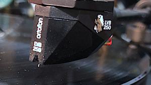
If You're Using an Oscilloscope to Set Azimuth Here's a Really Handy Program Courtesy WAM Engineering

If you're using an oscilloscope to set azimuth you are well aware of the math hassles involved. First you have to convert the derived voltages into dBVolts then you have to subtract the smaller number from the larger to determine the crosstalk and you have to do it twice: L-R, R-L.

Of course you need to do this at least five times starting a few degrees on one side then one degree off and then with the headshell parallel to the record surface and then twice more to the other side, each time doing the math.

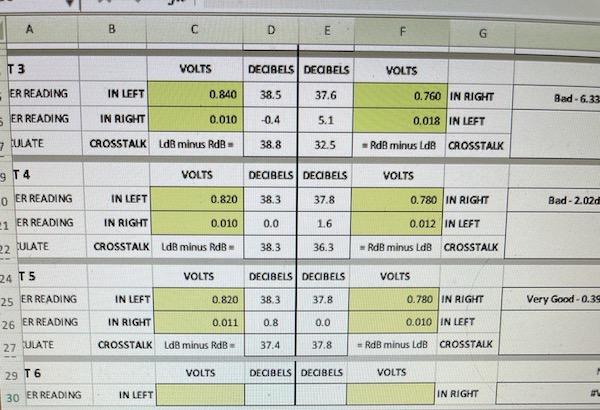
Now, thanks to WAM Engineering's Excel-based program you just plug in the numbers read off the oscilloscope and it does the volts to dBV calculations and all of the math. It makes the procedure so much easier!

Download it here

To use, simply type in the left channel meter reading, hit return, type in the smaller crosstalk reading from the right channel meter and hit return. You'll instantly see the crosstalk measurement in decibels! Repeat for the right channel measurements, always remembering to hit return after each entry and you'll get the right channel crosstalk measurement. If you're inter channel crosstalk maasurement is above 2dB it will say "BAD"!

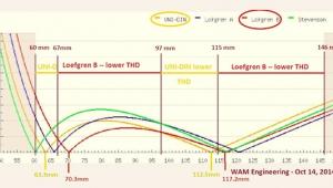
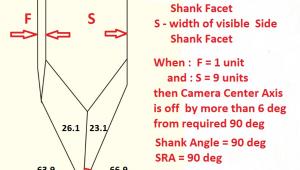
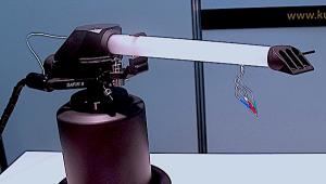
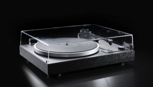
As you can see in the image at the top, the first set of readings produced a 6dB differential between the channels, earning it a "BAD" reading. By the 3rd measurement set shown, the separation was an outstanding 37 dBs in both channels with a crosstalk differential of .3dB, which is outstanding!

Please also read the "Important Notes" in yellow along the bottom of the field. Thank you WAM Engineering!

COMMENTS
Hosta3's picture

Thank you for the useful spreadsheet. Together with my old Tek 314, I hope not to purchase a $400 Fozgometer.

vince's picture

What a hoot! I just bought a Fozgometer about a week ago, specifically because the 'scope method is a pain. I can tell you it is fast and easy, the Fozgometer, that is, so I don't regret my purchase. I have an old HP 'scope, so it isn't light weight.

abelb1's picture

Can this be used with a multimeter? Would you connect meter to the preamp output or directly to the tonearm cable? (Assuming low output MC).
Thanks!

WallyTools - WAM Engineering LTD's picture

See here for instructions on how to use a digital multimeter for this measurement: https://www.analogplanet.com/content/crazy-little-thing-called-azimuth-p...

miguelito's picture

You should use a multimeter with AC RMS reading, connect it to the output of your phono pre (you want a cart that is properly loaded and a higher output), and I would suggest you use only one of the channels in your phono pre by reversing the input RCAs when you're switching channels - this way you guarantee same exact gain in the phono pre stage.

Gojira's picture

i much prefer to agree with Marc Gomez's recommendation that it is better to adjust the azimuth optically in relation to the surface of the turntable platter with microscopic inspection. If one adjusts the azimuth with a test record and uses an oscilloscope for this purpose, one can set an optimal adjustment in relation to this one record only. Records, however, turn out to be the complete opposite of high-precision sound carriers with the smallest manufacturing tolerances. If, when cutting such a record, even one mechanical parameter deviates slightly from the optimum, this error is then transferred to the azimuth setting. And how do you want to check how well the test record was made? If, on the other hand, the azimuth is set with enormous optical magnification on the flat surface of the platter, one can never be sure how perfectly the grooves of records are aligned with it, but one can be very sure that the needle, no matter how crookedly it may be installed in the cartridge, is perfectly aligned at right angles in relation to the surface on which the records lie. This would be the one advantage. Another advantage is that you take the measurement of this type when the tonearm is at rest. Measuring this value using a test record and oscilloscope, on the other hand, adds other mechanical influences that come from the operation of the tonearm, and can affect a very accurate measurement. For example, antiskating can never be perfectly adjusted because of the constantly changing groove modulation and will influence the measurement results. In addition, only very few tonearms play without interference. I performed this procedure on my system with a camera and an extremely magnifying macro lens. On the computer, i could then measure the needle angle and correct it on the tonearm. Just like you do this with SRA Setting. If the azimuth deviates even a microscopic amount from the perpendicularity, the spatial sound, three-dimensionality and detail resolution immediately collapse. With this variant of setting the azimuth, i have achieved results that surpass anything and the sound appears to be the optimum. If you don't have a macro lens or microscope, a DSLR with a macro reversing ring ($40 +/-) and a standard lens will do the job very good.

miguelito's picture

At the end of the day, what you really want is the needle reading the groove as aligned as possible. There can be many subtleties in how the diamond is cut or mounted that might throw this off. A test record such as the Analogue Productions Test LP is cut very carefully and has the right tracks (left only, right only) to do this adjustment properly.

WallyTools - WAM Engineering LTD's picture

The major radius on the stylus offers the freedom to have a "tilted" stylus riding the groove without having any deleterious effects. There is no USB scope capable of sufficient resolution and magnification to visually align the contact edges of stylus anyway. Within reasonable limits offered by that major radius, I don't care about the cantilever or the stylus shank being vertical as neither of them read the grooves - the contact edges of the stylus do.

If you research the tolerances with which these styli are cut and mounted, you'll see that it is not reliable at all to use any other proxy (cantilever or even the stylus' shank) as a means to visually align. A "tilted" stylus on the azimuth axis only results in a slight difference between the vertical position within the left and right grooves walls that the stylus is in contact with. Since each groove wall is uniformly shaped on the vertical (more specifically, cutting rake) axis, it doesn't matter that the left and right walls are contacted at slightly different spots on the vertical.

Adjusting on the azimuth axis is all about maximizing channel separation. Watch the video on this blog article so you can see why this is so: https://www.wallyanalog.com/post/finally-a-video-explaining-azimuth

You are correct about those test records AND about the variation of the cutterhead stylus on the azimuth (or any) angle. However, despite some sloppiness in the industry, we KNOW what the ideal azimuth cutting angle SHOULD be - perfectly perpendicular to the lacquer - and yet this does NOT set our target for the playback stylus! This sets the target for the angular relationship between the 45 degree groove wall and the coil in the magnetic flux field. See the video in the link above for the animation of this.

I have tested test records and have found an unacceptable variation between them of where each would have me set the azimuth angle (which I can measure to about 0.125 degrees). If we can assume that the cutterhead stylus is equally likely to err clockwise as it is to err counterclockwise, then we can infer that the records in the center of the distribution curve (with respect to the azimuth angle they would have us use) are the ones most likely to be setup at the lathe correctly. I have not tested every test record, but I can say that of the ones currently in print, you'd do well to "buy American" in order to remain in the center of that distribution curve. I'll do a video and blog post about this in the future. This is not an endorsement of those "center distributed" test records generally (I cannot agree with many of the cutting amplitudes being used) but for the measurement of crosstalk, the suggestion holds true so far.

Rake error, zenith error and excessive horizontal forces caused by too much skating force or too much anti-skating force will impact crosstalk results and, therefore, your ideal azimuth angle. There is a sequenced process one should go through to eliminate those variables. I go into that in another video on our channel.

jazz's picture

The only thing where other experts I spoke to (including the manufacturers of azimuth adjustment tools like of the Fozgometer and the Sperling Audio PDM-1) differ, is, that they say, the azimuth measurement tools are meant to check if the cartridge is properly manufactured. Most say, the cartridge should just be twisted very slightly from upright position for channel separation optimization. If more is necessary, the cartridge should be returned. A strong twisting of the cartridge should not be done for pure channel separation purposes, risking a problematic strain of the cantilever/suspension and stylus.
They say azimuth measurement is meant to ensure the ideal channel separation is very close to upright cartridge position, otherwise to know about the need to return the cartridge.

WallyTools - WAM Engineering LTD's picture

I agree with this. The “target” alignment is orthogonal to the record surface. However, we need to be specific about what angular deviation becomes “too much”. I realize that it is partly a product of the major radius, but manufacturers don’t release this information. WallyReference is the only tool I’m aware of that allows you to measure that angle. I measured a $13k cartridge yesterday that has a 70 micron major radius. At a perfectly level headshell the crosstalk was 27dB/28.2dB. Since I knew that the manufacturer spec was for 30 dB channel separation I continued to change the azimuth angle on this cartridge until I ended up with 31.2dB/31.6dB. At that point it was 1.85° off orthogonal. Is this acceptable? I say absolutely yes.

We must expect both the stylus/cantilever manufacturers and the cartridge manufacturers (not the same) to work within tolerances. The best stylus/cantilever designs I’ve seen have a +/-1.5° tolerance between the stylus and the coil former alignment. Of course that assembly needs to be mounted within the cartridge body within tolerance as well, so it could be further off the mark. This is exactly why we measure electrically!

miguelito's picture

Firstly, I have yet to see a detailed explanation or video - Mr Fremer pls do a video - of how this is ACTUALLY done with a scope.

What I do is:
Use the Analogue Productions LP left-only and right-only 1KHz signal tracks
1- Using the left-only track, I look at the right channel signal on the scope and take a snapshot (with my phone of the snap feature in my scope) of what I see
2- I reverse the leads going into my phono pre (left to right and right to left) and play the right-only signal and take a snapshot of the scope again. I reverse the phono leads from the turntable because I want to use the same channel for both measurements so that the gain is exactly the same.
3- Comparing the two I determine if there's an adjustment needed.
4- If I need an adjustment I shim the cart mount with folded aluminum foil - 10 folds. I have an SME V which does not allow for adjustment so I have to resort to this method - however, the precision of this method beats any screw method as none of those generally have a calibration scale.
5- With just two measurements - even if you went to the wrong side - you can interpolate to the right number of aluminum foil folds to get the exact azimuth.

One word about zenith: this is also not adjustable in the SME V. However, there's enough play in the screws that a small zenith adjustment can be made. The oscilloscope process is to read both channels of the output into two scope channels and find the zenith position that cancels the signal the most. You cannot generally do this on the phono pre if it is not fully balanced so you need to do the cancellation math on the scope.

One more comment about any of these: If your cartridge requires more than just a slight adjustment, your cart is fecked up and needs replacement. If any more than a slight adjustment is needed, you can imagine that aligning the stylus will cause a misalignment of the armature, so really get the piece of junk fixed.

WallyTools - WAM Engineering LTD's picture

…on aligning zenith with an oscilloscope but it is fraught with many problems, unlike the measurement of maximum stereo separation, which is fraught with just a few problems, most of which can be ameliorated by using the proper sequence of setup steps. Again, this is an issue I will write about and do a video on when I can make the time but for now suffice it to say that such a test is akin to having a multivariate test using multivariate references which, in the end, provide no certainty whatsoever. I will be writing instructions for a subjective evaluation of zenith error that I would trust more than a test record and an oscilloscope to do the same job. I’m not saying that the oscilloscope and test record can’t give you what *appears* to be useful information. I am simply saying that under these conditions optimization is far from certain. I’d prefer certainty so I can stop fiddling and just enjoy the music.

Gojira's picture

So swapping the channels seems like a suitable way to me. But I still have one question. How do you connect the transducers from the oscilloscope to the RCA connectors? Sorry, i am more on the mechanic than on the electric side. Thanks!

Elubow's picture

I have to confess that discussions like this make me dizzy. I think few here would disagree that the ultimate intention of this hobby is to derive pleasure from playing music. There are many ways to go about this. By in large, those commenting here seem very concerned with the minutiae, the mechanical aspects of vinyl playback, VTA, SRA, azimuth, etc. I’m not being dismissive when I say “”Good for them!” Each to his own!

When I think of my dad in the 1950s and 60s listening to music on his basement console and homemade speakers, it seemed to me, he enjoyed listening immensely. He had never heard of VTA, SRA.
azimuth. But he enjoyed the music regardless. How does one measure pleasure? Did he enjoy the experience less because his system was not as sophisticated as many of our overengineered turntables today? Or because he did not have footers for his cables or cables that cost thousands of dollars a foot? I would argue he enjoyed it more because he wasn't obsessed with GETTING EVERYTHING RIGHT, with achieving perfection. He just listened to the music and at times seemed transfixed. Who could blame him for that?

2_channel_ears's picture

I would give your post one. I am mildly interested in the tech but at the end of the day, I just want to listen to what I got.

WallyTools - WAM Engineering LTD's picture

I completely agree with that!

However, IF you are using a fine line contact stylus and it is not properly aligned then it is a mechanical certainty it will not retrieve all of the information there is to get out of the groove.

We can resolve (hear) groove surface content that is in the high double digit/low triple digit nanometer range. That is LESS THAN THE WAVELENGTH OF LIGHT. This groove content cannot be fully resolved if there are phase related issues - which is ultimately what stylus contact edge misalignment is about.

If you don't want to worry about it then don't! Simply enjoy analog forever! There is nothing wrong with that at all.

Glotz's picture

Back then.. Yes Shibata's were available on the Denon DL103, but most were conical styli that got the midrange right.

Today we get much more fidelity from more extreme profiles. And it therefore follows that we must be more precise.

WallyTools - WAM Engineering LTD's picture

I would argue, however, that Shibata styli are not true fine line contact profiles and do not behave in the groove in the same manner in which it was cut by the cutting stylus.

garyalex's picture

I agree with you. Life is short and there's so much great music I haven't yet heard.

SeagoatLeo's picture

This question concerns SME IV and V tonearms, How can I adjust azimuth, rake error and zenith error or are they not adjustable on those arms? I've been using my modified tonearms incorrectly per this discussion for 33 yeas and will never achieve great sound. However, none of my friends who own similar high(er) end analog setups ($5K to my $20+K, some with unipivots) do ajustments for those parameters and we all use line contact (one micro-ridge) stylii. We are meticulous in adjusting VTA, VTF and anti-skate. Sure, back in the 50s and 60s the choices were conical and elliptical, the former having few requirements. I guess we all have to suffer with good but not great sound, huh?

WallyTools - WAM Engineering LTD's picture

See here: https://youtu.be/DsWWiKrb2jY

Several British tonearm Manufacturers rightly put a priority on ultra rigid tonearm designs. I completely agree with this approach. However, in an effort to make no compromises on rigidity, some of them have decided not to offer a mechanism for azimuth adjustment. This is where I Disagree with the design priorities. Given a well-designed Azimuth adjustment mechanism, the very small amount of rigidity sacrificed is more than made up for by the ability to maintain maximum stereo separation.

There doesn’t have to be a debate about this without any certainty. A laser vibrometer would offer the definitive conclusion. We are casually shopping for them now.

It might be argued that cartridges are supposed to be manufactured such that a perfectly level cartridge top side would give you maximum stereo separation - and this would be true. However, in the last 80+ cartridges I have analyzed the average ideal azimuth angle deviation is 1.1°. We must accept the fact that cartridges and stylus/cantilever assemblies are manufactured with manufacturing tolerances. We cannot expect perfection, but at least at the nosebleed pricing levels it would be nice if they knew what they were selling us and reported for each individual cartridge at what angles we needed to adjust them for maximum performance.

Gojira's picture

Thank you for all the constructive suggestions.
First, I must repeat what I wrote at the beginning of my first comment.
I followed up on the following quote from Positive Feedback:

https://positive-feedback.com/reviews/hardware-reviews/swedish-analog-te...

Swedish Analog Technology (SAT) LM-12 Tonearm: Analog Playback Meets Rocket Science
07-01-2019 | By Myles B. Astor | Issue 104

From the second to last paragraph of the report at the very bottom of the page, here is what I found:

“Then it's onto setting cartridge azimuth. There are a number of different ways to set azimuth including the Fozgometer (that uses crosstalk) or software-based methods such as those from Feickert (that uses either crosstalk or phase) or the newer AnalogMagik (that uses distortion measurements). Marc, however, suggests (and recommends) setting azimuth optically for maximum performance and tracking accuracy.”

Yes, it is the Marc Gomez who makes the SAT tonearms.
Please do not misunderstand me. It is not about a religious war or to proselytize only my conviction. In the end, everything should only lead to the fact that we can extract the maximum from the grooves. And as we all know, there are many roads that lead to Rome.

Of course, it is not only a matter of the diamond's shaft being straight, but also of the lateral flanks of the needle, viewed from the front, both having exactly the same dimensions, i.e. the length of the angled surfaces in contact with the groove flanks, and both having exactly the same angle in relation to a straight surface. Thus, no method can be used to make optical checks of the needle flanks in relation to the groove flanks of the records during operation.
Of course, you are absolutely right that this is not all, however.
Because it also depends on the relationship between these geometries and the coils positioned on the cantilever at the rear. If the needle is at a right angle and the two angled flanks seen from the front have exactly the same dimensions and are formed at exactly the same angle, this does not mean that the needle is in exactly the same relationship to the coils. It is also very difficult to measure or visualize this. From therefore the point goes to you and I will use for comparison a measurement that you recommend and can but ultimately then evaluate the differences only sonically.

Due to the enormous problems in the production of these micromechanical systems, there are constantly inaccuracies even in cartridges for many thousands of dollars. From therefore I will compare the purely optical adjustment once with that of an oscilloscope and a test record.

But there is another background. With the method of an oscilloscope, it could well be that they get best measures for both channels. If you then use the optical method, however, it could very well be that the two edges that are in contact with the grooves are then skewed.
This misalignment then inevitably leads to asymmetrical wear of the needle. So it now suggests itself to us that no matter what we do, there are always imperfections we have to live with, both in the geometries of the products and in the adjustments we make. So far, my experience with the optical method has always been very clear audible. Nevertheless, I will also use your method, and I am already very curious about the differences.

Thank you very much for your detailed recommendations.

WallyTools - WAM Engineering LTD's picture

Feel free to reach out to me directly through my website to let me know how the electrical measurement goes for you. I am interested in your results. Keep in mind that where you have the cartridge right now may be the point of maximum stereo separation in which case you would’ve been very lucky. This is why I tell people to measure electrically before they purchase the WallyFulcrum. Just because you have no Azimuth adjustment mechanism it doesn’t mean you need one. In most cases, however, you do.

Lastly, there is no “length“ of stylus contact edge. The stylus contact edge is a radius. As long as the “tilt“ of the stylus shank does not exceed the ability of that major radius to maintain a tangential relationship with the groove wall, any stylus shank variation off of perpendicular with the record is just fine.

Gojira's picture

It might take me a while to get this done with the measurements. Probably you are right that I was certainly just lucky with my system, which probably keeps all geometrical parameters very well. It is an Audio Technica ATOC9XSL. I studied your website on azimuth and think I'll get to the bottom of it with your recommendations.
When I get the measurement results, I will contact you. I am already more than pleased with the very wide spatial extent and the floods of high detail resolution. But who knows, maybe I can get even more out of the grooves with your methods.

Thank you very much for your help.

Michael Fremer's picture
I will address both in an upcoming video. However, thus far the new Fozgometer (unlike the original) has proven to be 100% accurate. That is, when I set up azimuth using an oscilloscope, the Fozgometer's reading is 100% accurate. That's great news! However, for those who want to know the actual crosstalk figures (or close to them), only the oscilloscope will do.
Gojira's picture

now i learned many backgrounds from the website of wally tools. Thank you so much to share your knowledge. Can´t wait to do it the electrical way.

RaggaMuffin's picture

Thanks for sharing this, will be very helpful.

I was wondering if anyone can help me with something? When I've tried to set my azimuth before, I've used a Behringer audio interface and oscilloscope software. However, with the phono stage (Trichord Dino) at the normal and correct settings for my cart (Hana SL), when I measure a 1khz sine wave it's clipped, even with the gain set on the interface to the minimum. If I lower the phono stage gain so the waveform is not clipping, is it fine to then calculate the crosstalk as normal? Or should the settings on the phono stage be set correctly for the cart?

Also, when taking the voltage measurements for this software, should I be looking at RMS voltage or peak-to-peak?

Thanks in advance!

WallyTools - WAM Engineering LTD's picture

If the waveform is clipping you won't get good data. Confused by your comment "even with the gain set on the interface to the minimum" and then later you suggest later than you can lower the gain further. If you can lower it, do it until you no longer see clipping. If you see clipping in one channel only get a WallySkater to figure out what is going on with that tonearm.

RMS is what you are looking for

RaggaMuffin's picture

Thanks. Sorry, when I say 'lower the gain' I mean lower the gain on the phono stage by altering the dip switches. To not get a clipped waveform I have to lower the gain on my Trichord Dino to 'MM Low Output 2-3mV 42dB', whereas with normal playback I have it set at 'MC 63dB'.

liguorid42's picture

Why convert volts to dB at all? Isn't raw voltage ratio much more sensitive to changes than its logarithm?

Nordfinn's picture

Can someone help out a neophyte with this? What voltage readings does one use? My software 'scope (Soundcard Scope) gives peak-to-peak, in "m" (which I can only assume is millivolts) and effective voltage (which I take it is the same as RMS?), also in "m." Thanks very much, N.

X